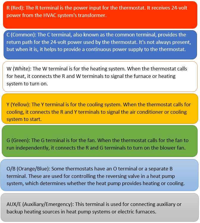
Understand the wiring colors and the function of each wire

2 Wire Thermostat Wiring
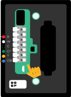
1) Attach the Red wire to the R terminal for 24V Power – or to the RC terminal if that is where it was on the old thermostat.
2) Attach the White wire to the W terminal for Heating.
3 Wire Thermostat Wiring
1) Attach the Red wire to the R terminal for 24V Power – or to the RC terminal if that is where it was on the old thermostat.
2) Attach the White wire to the W terminal for Heating
3) Follow the label from the original thermostat to confirm if remaining wire is for Fan or as Common. If the wire is Green, attach the wire to the G terminal for the Fan. If remaining wire is either Black/Blue, it may be used as a C Wire
4 Wire Thermostat Wiring
1) Attach the Red wire to the R terminal for 24V Power – or to the RC terminal if that is where it was on the old thermostat.
2) Attach the White wire to the W terminal for the heat pump’s Heating mode.
3) Attach the Yellow wire to the Y terminal for AC/cooling mode.
4) Attach the Green wire to the G terminal for the Fan
5 Wire Thermostat Wiring
1) Attach the Red wire to the R terminal for 24V Power.
2) Attach the White wire to the W (or W1) terminal for the heat pump’s Heating mode.
3) Attach the Yellow wire to the Y terminal for AC/cooling mode.
4) Attach the Green wire to the G terminal for the Fan.
5) Attach a “spare” wire to the C terminal – such as the Black/Blue wire for C or Common.
6 Wire Thermostat Wiring
1) Attach the Red wire to the R terminal for 24V Power.
2) Attach the White wire to the W (or W1) terminal for the heat pump’s Heating mode.
3) Attach the Yellow wire to the Y terminal for AC/cooling mode.
4) Attach the Green wire to the G terminal for the Fan.
5) Attach a “spare” wire to the C terminal – such as the Black wire for C or Common.
There are a few options for step 6:
6) If it is a single stage heat pump but has Aux heat strips in the air handler, attach an unused wire, such as the Light Blue wire, to the X/Aux terminal for Auxiliary heat.
0r:
6) If the heat pump has two stage cooling, attach the Light Blue wire to the Y2 terminal for 2 Stage Cooling.
Or:
6) If the heat pump has two stage heating, attach the Brown wire to the W2 terminal for 2 Stage Heating.